
The generation and prevention of electrical surges in integrated circuits
Release time:
2021-01-09
One of the most common failure modes of devices during use is damage or burnout caused by electrical overload (EOS) due to electrical surges.
One of the most common failure modes of devices during use is damage or burnout caused by electrical overload (EOS) due to electrical surges. Below is a brief discussion on the generation and prevention of electrical surges in integrated circuits.
1. What is an electrical surge (electrical overload EOS)
Fluctuations in the power grid, changes in circuit states, external interference signals, and failures of neighboring components can all generate high peak current or voltage pulses in the circuit, known as electrical surges (electrical overload EOS). Electrical surges can cause devices to operate instantaneously beyond their maximum rated values. The average power of an electrical surge is small, but its instantaneous power is large enough to cause device failure. Sometimes lower power surges can also lead to device latch-up or CMOS circuit latch-up effects resulting in failure. Failures caused by electrical surges account for more than 50% of failures in integrated circuits.
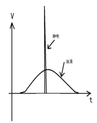
2. The difference between electrical surges and static electricity
The difference between static electricity and electrical surges lies in that static electricity has high voltage but low energy, while surges have relatively high energy. Therefore, there are no visible failure points on the surface of circuits affected by static electricity, and power consumption does not exceed limits. In contrast, damage from electrical surges is often visible during cap inspection and usually accompanies an increase in power consumption.
The destruction of a device due to abnormal electric stress relies not on how much voltage the device experiences but on how much Joules of thermal energy that electric stress generates on the device. It's like saying a person standing under a high-voltage transmission line at tens of kilovolts is fine, but touching 220V AC would be dangerous.
Joule's Law: The thermal energy generated across a purely resistive load:
Q=W=Uit=U²/R×t
If R=5Ω, U1=1000V (static electricity), t1=1us (static electricity), then the thermal energy generated by static electricity on a semiconductor is:
Q1=1000²V/5Ω×1uS=200 millijoules
If R=5Ω, U2=50V (electrical surge), t2=100ms (electrical surge), then the thermal energy generated by an electrical surge on a semiconductor junction is:
Q2=50²V/5Ω×100mS=50 Joules
3. Causes of electrical surges in circuits
(a) Surge current generated when capacitive loads are connected. When switching circuits drive capacitive loads and there are sudden voltage changes in the circuit, since voltage across capacitors cannot change instantaneously, it generates a momentary current for charging the capacitor.. For example, if a regulator has a large capacitor connected at its output while no capacitor is connected at its input, an extremely large current will be generated at the moment power is applied, burning out the regulator.
(b) Surge voltage generated when inductive loads are turned off. When transitioning from an open state to a closed state in a circuit due to inductance where current cannot change instantaneously, it generates a surge voltage that opposes current change..
(c) When using input or output transformers in circuits, very high voltages can be induced under open-circuit conditions at either primary or secondary sides leading to damage at input or output stages.
(d) Fluctuations in grid voltage, especially sudden outages and restorations can also generate significant surge voltages and currents.
(e) Due to wiring errors or operational mistakes such as incorrect powering sequence leading certain transistors to forward breakdown or reverse breakdown not only deteriorates transistor characteristics but also causes surge currents.
(f) Digital circuit transitions can generate surge currents. During transitions within digital circuits where some transistors switch from conducting to non-conducting while others switch from non-conducting to conducting simultaneously creates surge currents within the circuit.
4. Prevention of electrical surges
(a) Correct usage of integrated circuits including proper connections, powering sequences, shutdown sequences, testing procedures and operational methods etc. Carefully check peripheral electronic components to prevent failures that could lead to surges.
(b) For circuits generating surge currents, it’s advisable to insert appropriate inductors or resistors for mitigation.
(c) For circuits generating surge voltages, it’s advisable to parallel with a resistor or diode (the diode should conduct during voltage surging).
(d) Design according to integrated circuit specifications ensuring all necessary components such as damping capacitors and power filtering capacitors are included without omission.
(e) Avoid open-circuit conditions at primary side transformers and secondary side transformers; if necessary parallel with resistors or capacitors.
Key words:
Next Page
Next page:
recommend News
Understanding High-Speed Amplifiers for Efficient Data Acquisition
High-speed amplifiers are essential in the field of data acquisition, particularly for applications that require rapid signal processing and high accuracy. These amplifiers are designed to boost weak electrical signals, making them more suitable for analysis and further processing. Key applications of high-speed amplifiers include scientific research, industrial automation, telecommunications, and
2026-07-02
Wideband Amplifiers: Bridging the Gap in Communication Technology
Wideband Amplifiers: Bridging the Gap in Communication Technology Table of Contents 1. Introduction to Wideband Amplifiers 2. What Are Wideband Amplifiers? 3. The Importance of Wideband Amplifiers in Communication Technology 4. How Do Wideband Amplifiers Work? 5. Applications of Wideband Amplifiers 6. Key Benefits of Using Wideband Amplifiers 7. The Future of Wideband Amplifiers in
2026-07-01
Essential Insights on Power Amplifiers for Motor Control Applications
Power amplifiers for motor control are vital components in various electronic systems, serving as the bridge between low-level control signals and the high-power requirements of motors. These amplifiers are designed to deliver significant power gains, enabling precise control over motor speed, torque, and direction. Understanding their functionality and selection criteria can greatly enhance the p
2026-06-30
Common Mistakes to Avoid When Using Rail-to-Rail Amplifiers
Common Mistakes to Avoid When Using Rail-to-Rail Amplifiers Rail-to-rail amplifiers are powerful tools in the electronics industry, enabling designers to maximize the output signal range of their circuits. While these amplifiers can significantly enhance performance, many users make common mistakes that can lead to suboptimal results. In this article, we will delve into these pitfalls, providing v
2026-06-29
Unlocking the Potential of Rail-to-Rail Amplifiers in Sensor Interfaces
Rail-to-rail amplifiers are pivotal components in modern electronic systems, particularly in sensor interfaces where precision and efficiency are paramount. These amplifiers are designed to operate over the full voltage range from the negative rail to the positive rail, enabling them to effectively utilize the entire supply voltage. This characteristic is especially beneficial in applications requ
2026-06-28