
The generation and prevention of electrical surges in integrated circuits
Release time:
2023-06-12
One of the most common failure modes of devices during use is electrical overload (EOS) damage or burnout caused by electrical surges.Below, we briefly discuss the generation and prevention of electrical surges in integrated circuits.
1. What is an electrical surge (electrical overload EOS)
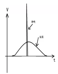
Fluctuations in the power grid, changes in circuit status, external interference signals, and failures of neighboring components can all generate high peak current or voltage pulses in the circuit, known as electrical surges (electrical overload EOS). Electrical surges can cause devices to operate instantaneously above their maximum rated values. The average power of a surge is small, but its instantaneous power is large enough to cause device failure. Sometimes lower power surges can also lead to device self-excitation or CMOS latch-up effects resulting in failure. Failures caused by electrical surges account for more than 50% of failures in integrated circuits.2. The difference between electrical surges and static electricity
The difference between static electricity and electrical surges lies in that static electricity has high voltage but low energy, while surges have relatively high energy. Therefore, there are no visible failure points on the surface of circuits affected by static electricity, and power consumption does not exceed limits. In contrast, damage from electrical surges is often visible during cap inspection and usually accompanies an increase in power consumption.
An abnormal electric stress burns out a device not based on how much voltage the device experiences but rather on how much Joules of thermal energy that electric stress generates on the device. It's like saying a person standing under a high-voltage transmission line at tens of kilovolts is fine, but touching 220V AC would be dangerous.
Joule's law: The thermal energy generated across a purely resistive load:
Q=W=Uit=U²/R×t
If R=5Ω, U1=1000V (static electricity), t1=1us (static electricity), then the thermal energy generated by static electricity on semiconductors is:
Q1=1000²V/5Ω×1uS=200 millijoules
If R=5Ω, U2=50V (electrical surge), t2=100ms (electrical surge), then the thermal energy generated by an electrical surge on semiconductor junctions is:
=50²V/5Ω×100mS=50 Joules
3. Causes of electrical surges in circuits(a) Surge current generated when capacitive loads are connected. When switching circuits drive capacitive loads and there are voltage transients in the circuit, since the voltage across the capacitor cannot change instantaneously, a momentary current for charging the capacitor will be generated.(b) Surge voltage generated when inductive loads are turned off. When a circuit transitions from an open state to a closed state, since current through an inductor cannot change instantaneously, a surge voltage will be produced across the inductor that opposes changes in current.
(c) When using input or output transformers in circuits, very high voltages can be induced under open-circuit conditions at either primary or secondary sides leading to damage at input or output stages.
(d) Fluctuations in grid voltage, especially sudden outages and restorations can also produce significant surge voltages and currents.
(e) Due to wiring errors or operational mistakes such as incorrect powering sequence leading to forward breakdown or reverse breakdown of certain transistors within circuits not only deteriorates transistor characteristics but also causes surge currents.
(f) Digital circuit transitions can generate surge currents. During digital circuit transitions, some transistors switch from conducting to non-conducting while others switch from non-conducting to conducting simultaneously causing surge currents within the circuit.
4. Prevention of electrical surges
(a) Correct usage of integrated circuits including proper connections, powering sequences, shutdown sequences, testing procedures and operational methods etc. Carefully check peripheral electronic components to prevent failures that could lead to surges.
(b) For circuits generating surge currents, it is advisable to insert appropriate inductors or resistors to mitigate them.(c) For circuits generating surge voltages it is advisable to parallel with a resistor or diode (the diode should conduct during voltage surging).
(d) Design according to integrated circuit specifications ensuring all necessary components such as damping capacitors and power filter capacitors are included.
(b) For circuits generating surge currents, it is advisable to insert appropriate inductors or resistors to mitigate them.(e) Avoid open-circuit conditions at primary side transformers and secondary side transformers; if necessary parallel with a resistor or capacitor.
(b)对于产生浪涌电流的电路,原则上串入适当的电感或电阻来加以消除。
(c)对于产生浪涌电压的电路,原则上并联一个电阻,或一个二极管(电压浪涌发生时二极管应导通)来加以消除。
(d)设计中按集成电路使用说明书进行电路设计,该使用的元器件一定不要少,如消振电容、电源滤波电容等。
(e)避免输入变压器初级和输出变压器次级开路,必要时,可并联一个电阻或电容。
Key words:
Next Page
Next page:
recommend News
Future-Proof Your Communication Systems with Wideband Amplifiers
Future-Proof Your Communication Systems with Wideband Amplifiers Table of Contents Understanding Wideband Amplifiers: A Comprehensive Overview The Importance of Wideband Amplifiers in Communication Systems Key Benefits of Using Wideband Amplifiers Applications of Wideband Amplifiers in Various Industries How to Select the Right Wideband Amplifier for Your Needs Future Trends in Wideba
2026-10-06
Understanding Power Amplifiers for Motor Control: Essential Insights for Electronics Enthusiasts
Power amplifiers for motor control are pivotal components that enhance the efficiency and performance of electric motors. They take low-power control signals and amplify them to a level sufficient to drive a motor effectively. This amplification is essential for applications that require precise control over motor speed, torque, and position, making power amplifiers vital in industries ranging fro
2026-10-03
Integrating Rail-to-Rail Amplifiers: Essential Tips for Seamless Circuit Implementation
Integrating Rail-to-Rail Amplifiers: Essential Tips for Seamless Circuit Implementation Rail-to-rail amplifiers have become essential components in modern electronic designs. Their ability to operate over the entire supply voltage range makes them particularly useful in low-voltage applications. In this article, we will explore various strategies for integrating rail-to-rail amplifiers effectively
2026-09-30
Understanding Rail-to-Rail Amplifiers for Sensor Interfaces: A Comprehensive Guide
Rail-to-rail amplifiers are a vital component in the realm of sensor interfaces, providing a crucial link between sensor outputs and the processing units that interpret those signals. Their primary advantage lies in their ability to utilize the full supply voltage range, which is particularly important in battery-operated devices where every millivolt counts. By maximizing the output swing, rail-t
2026-09-27
Troubleshooting Tips for Low Voltage Rail-to-Rail Operational Amplifiers
Troubleshooting Tips for Low Voltage Rail-to-Rail Operational Amplifiers Table of Contents 1. Introduction to Low Voltage Rail-to-Rail Operational Amplifiers 2. Common Issues with Rail-to-Rail Operational Amplifiers 3. Diagnosing Problems: Step-by-Step Approach 4. Power Supply Issues and Solutions 5. Signal Integrity Problems in Low Voltage Applications 6. Component Select
2026-09-24