

Study on Current-to-Voltage Conversion Error in Quartz Flexure Accelerometers
Release Date:
2023-06-12
Source:
Author:
As a mature, high-precision inertial accelerometer, the quartz flexure accelerometer can output 10 -5 g~tens of grams To ensure the overall accuracy of the system, the corresponding accelerometer acquisition circuit should also minimize its own introduced errors and enhance data‑acquisition performance.
Since quartz flexure accelerometers output current signals via analog control, and modern data acquisition systems require digital signals, it is necessary to convert these analog current signals into digital form. As the accuracy of quartz flexure accelerometers continues to improve, maintaining distortion-free signal reconstruction becomes increasingly critical, making the design of high‑precision analog‑to‑digital conversion circuits particularly important.
Currently, there are two methods for implementing this type of analog-to-digital conversion, namely: The A/D converter performs analog-to-digital conversion by conditioning the current signal into a frequency signal and then implementing frequency counting, thereby achieving I/F conversion. When an A/D converter is used for signal conversion, a current-to-voltage conversion stage is required. To enhance the performance of the data acquisition circuitry for a quartz flexure accelerometer, the errors introduced by this current-to-voltage conversion stage—being the first stage in the acceleration‑measurement system—cannot be ignored. Selecting an appropriate conversion method plays a crucial role in improving the overall accuracy of the inertial measurement system.
In the current–voltage conversion stage, a precision, low‑temperature‑drift shunt resistor is required; however, this introduces a loading effect. The loading effect refers to the shunting of the accelerometer’s output current caused by the current–voltage conversion, which not only degrades conversion accuracy but also reduces the conversion rate.
The currently commonly used current-to-voltage conversion is Direct conversion, instrumentation operational amplifier conversion, and current-to-voltage converters, The following provides a comparative analysis of these three conversion methods.
1 Direct conversion

Figure 1: Equivalent Circuit of Direct Conversion Impedance
Note: The input resistance Ri is the equivalent impedance of the downstream passive low-pass filter or the input impedance of the active low-pass filter.
According to Kirchhoff’s Current Law, Io = Is + Ii, which causes the output voltage Vout to be lower than its theoretical value.
Actual measurement

The smaller the input resistance Ri, the greater the output voltage deviation. The actual measured value is only a fraction σ of the theoretical value:

If the shunt resistor Rs is 1 kΩ and the input resistance Ri is 50 kΩ, then the measured value will be only 98.04% of the theoretical value.
2 Instrumentation Operational Amplifier Conversion

Figure 2: Schematic Diagram of Instrumentation Operational Amplifier Conversion
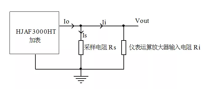
Similarly, the instrumentation operational amplifier configuration can also be equivalently represented by the impedance equivalent circuit shown in Figure 3.
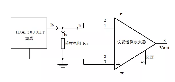
Figure 3: Equivalent circuit diagram of the instrumentation operational amplifier’s transimpedance.
When using an instrumentation operational amplifier for signal conversion, the choice of device has a significant impact on conversion accuracy. Conventional instrumentation op amps typically have input resistances on the order of several hundred megohms, whereas high‑performance models can achieve input impedances as high as 10 GΩ to 100 GΩ; under these conditions, the conversion accuracy can be considered to approach its ideal value.
Additionally, the instrumentation operational amplifier can be zeroed via the REF pin (with a low‑impedance input), thereby reducing the system’s offset and improving measurement accuracy.
3 Current-to-voltage converter
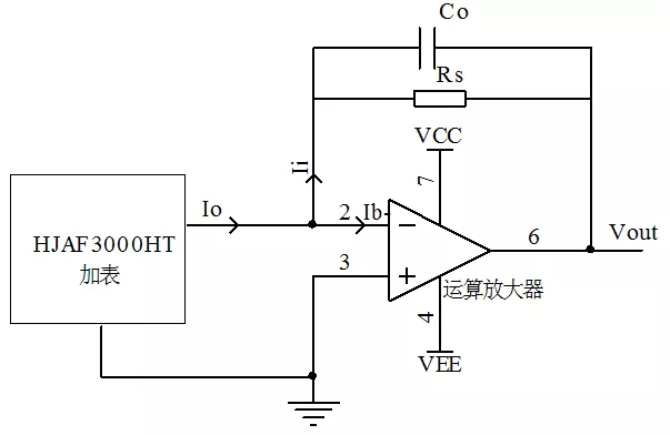
Because high‑precision operational amplifiers have very small input offset currents, we can assume Ii = Io. Consequently, the current‑to‑voltage converter eliminates errors arising from load effects, achieving a conversion accuracy approaching 100%.
When using the current-to-voltage converter method, the output terminal L‑ of the ammeter always operates at a “virtual ground” point, which enhances its resistance to vibration and shock, expands its linear operating range, and improves its survivability in harsh environments.
When using a current-to-voltage converter, it is necessary to select an operational amplifier with low offset current, high slew rate, and strong output current capability. Additionally, the current-to-voltage converter can function as a low‑pass filter; within the low‑frequency range of the acceleration output, by choosing appropriate resistor and capacitor values, its impact on the output can be neglected while still providing low‑pass filtering. 。
In summary, direct conversion exhibits excessive conversion error and is therefore not recommended; both differential amplifier‑based conversion and current‑to‑voltage converters can eliminate load effects while exerting minimal impact on sensitivity.
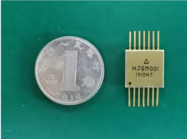
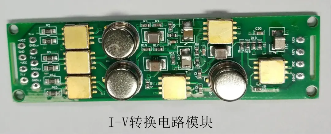
In response to customer needs, our company has developed two products: the HJGM001 (instrumentation operational amplifier conversion type) and a three-axis accelerometer I‑V conversion circuit module (current‑to‑voltage converter type). We welcome you to place your order!
Keywords:
Hot News
Leave a Message Online
*Note: Please ensure that all information provided is accurate and keep your contact details up to date. We will get in touch with you as soon as possible.
Request for Samples / Product Manuals / Contact Information:
Mr. Jia:13022932841(WeChat)
Landline:029-89259995Transfer 833
Technical Support / Contact Information:
Mr. Zhao:13572473285
Landline:029-89259995Transfer to 803
Ms. Xu:18729396827
Company landline:029-89259995
Fax: 029-89259996
Unit 4, Building 6, Beihang Science and Technology Park, Hangtian Middle Road, Aerospace Base, Chang’an District, Xi’an, Shaanxi Province
